All posts by admin

Samsung LN40C530 Flickering Backlight

This problem seems to affect the following models as well

  • LN40C530 LN40C530F1F LN40C530F1FXZC
  • LN46C530 LN52C530
  • LN46C630

There are some guides online indicating cutting JP852 on the power supply board will fix this problem.  This fix disables protection circuitry and probably is not an ideal solution.

Posts on badcaps and avsforum indicate the real problem is low voltage caused by bad surface mount resistors in the power factor correction (PFC) circuit dropping the backlight voltage from a nominal 390VDC to 350VDC.  This voltage can be measured across the large filter cap on the board (use the negative leg as ground).  These are lethal and high voltages so be careful when taking this measurement.

I replaced the four series 1.5M ohm 0805 1% resistors (RP802, 805, 807,810) and the voltage came back up to 395VDC from around 360VDC.  Measuring the original resistors still indicated 1.5M ohm resistance though the discrepancy probably comes from the higher voltage applied in the circuit.

The design places multiple resistors in series because maximum voltage for an 0805 resistor is around 150V and max power is 125mW.  Calculated power dissipation is 6.7mW which well below the rating.

LG 50PV400 50PV450 Plasma Clicking Won’t Turn On

Though I was avoiding plasma TV’s due to their weight and lower resale value, I did get a hold of this one which was a bit newer.  Research indicated the 50PV400 is a Costco version of the 50PV450 and pretty much identical.

Plasmas contain lethal high voltages so you need to be extra careful working with one which is currently or recently plugged in.   I was able to find a training manual for the 50PV450 here.

This TV would not turn on and you could hear the relay click when the power button was pressed.  Measuring the voltages on the power supply connector to the main board indicated the voltages were present but the power supply was performing a self-shutdown due to a fault somewhere.

Measuring the resistance of the high power output voltages going to the display (VS, VA and M5V) found a short on the VS line.  The short was traced to the ZSUS board and close inspection of the board found a entire row of components under a heat sink with scorch marks at their bases.  These parts were FGP4633 IGBT transistors (Q106, Q109, Q107 & Q110) and RD2003 diodes (D114 & D118).  Checking the diodes and transistors in-circuit with a multimeter indicated they were all shorted.

Replacement FGP4633 transistors can be found on Ebay or Mouser but not Digikey.  I wasn’t able to find an equivalent for the diodes.  I ended up ordering a replacement ZSUS board since they were under $20 USD on Ebay.

Update: I got the replacement board and the TV powered on but the picture was splotchy.  Not sure if there was a problem with the zsus board or if the problem was elsewhere.

TWRP Can’t Find Restore Files Solution

I ran into this problem after replacing the main board of my Asus ME301T tablet.  I successfully installed TWRP but it couldn’t find my backups that I have saved on SD card.  Being impatient, I just reinstalled Lollipop, all my apps and restored app data with the Helium app.

Researching this afterwards, I found this youtube video.

The problem is that TWRP creates a subfolder under BACKUPS based on the device’s serial number. By changing the main board, the serial numbers no longer match. The trick here is to do a new small backup (backup the cache only) which will create a new backup folder with the device’s new serial number.  Write down the name of it, delete it and rename your old backup folder the same name. TWRP should now see your backup files. You can perform all these file operations using the file manager in TWRP.

The device’s serial number can also be found under Settings->About Tablet->Status

Citizen C27604HD TV No Power

I was able to find a service manual for a Viewsonic N2751W which appears to have the same hardware.  It can be downloaded from here.  A better power supply schematic can be found here.

The usual suspect for power issues are bad electrolytic caps.  It took me a while to get the back cover off since it was being help in place by clips.  I had to push in the sides of the back cover to release it.

Inspecting the power supply board, I found four bulged capacitors.  2 x 1500uF/16V, 220uF/25V and 220uF/35V.  These were all capxon brand.  I replaced the non-bulging capxons as well which were 2 x 1000uF/25V and 220uF/16V.

When I reinstalled the board, I still had no power so I googled the board part number FSP 212-3F01 (3BS0118510GP).  This board is used in several TV’s including Hanspree JT01-32U1-000G and Viewsonic models N2635W, N2751W, N2752W, N3235W, N3250W, N3251W and N3252W.

Q7 and ZD4 are usual suspects with no power since these parts provide 5V DC standby.  Checking Q7 with a multimeter showed it was shorted base to collector.  A good BJT transistor should have a diode drop between base to emitter and base to collector.  You do have to be careful working with the power supply board when it is plugged in since the majority of it is hot and you can get a shock even from touching the ground.  ZD4 should have 15V DC across it.

I replaced Q7 – MMBT4401 (Digikey #MMBT4401LT1GOSCT-ND) and ZD4 (Digikey #1727-4962-1-ND).  I also decided to replace all the remaining smaller capxon caps 33uF/35V (3), 2.2uF/50V,  10uF/50V and the two remaining Taicon 1000uF/35V caps.

Once power was back up, I had some issues with the remote control not working.  I was able to get it working by performing a factory reset.  With the TV on, press the power button in the front,  and up and enter keys on the top at the same time (all three together) to bring up the service menu.  Select EEPROM Init to perform the reset.

Ebay Pencil Butane Burner Review and Repair

I had purchase this tool for a couple of bucks on Ebay to repair surface mount components.  It heats up very quickly and it is very easy to burn a board with it.  I would practice with some junk boards and heat up slowly (by keeping the flame away) from underneath the component you want to remove or solder.  Removing components is a bit easier if you don’t care about damaging the board.

After a couple of uses, the tip appeared clogged since no gas was coming out.  Checking the package, there are maintenance instructions that indicate “To clean the torch, slip off the burner and release a few shots of butane directly into the orifice to clear it of unwanted particles.”  Since this was unclear, I googled the problem and found this instructable.

The head of the burner can be unscrewed from the narrower shaft.  I had to use vice grips and a bit of force to get it off.  There is a bit of red thread sealer holding it in place.

A small, thin metal disc came out and this piece is important to put back in once you clear the head.  It acts like a water reducer in a shower head.  Without it, the butane comes out at lower pressure and the flame will be like a big lighter instead of a concentrated flame.

Motorola DCX3400M DVR Loses Guide Data After Firmware Update

My DVR got a firmware update about a month ago which changed the default background colour to black and the menus went from standard width to widescreen.  However, it became unstable and would periodically freeze and lose all the guide data.  This could happen within hours or days.  I unplugged it a few times and patiently waited for another update but finally contacted the cable company.

They indicated they hadn’t had reports of issues but could send a reset signal.  However, this signal would wipe out all my scheduled recordings.  I told them I would find a solution on my own.  With my previous generation Motorola DCT64xxx, you could force download of new firmware by holding down the power and menu buttons while plugging it in.  There is a guide here

With the DCX3400, the buttons are soft but I was able to find the alternate procedure in a forum.  When you plug in the AC, the front display will display 88:88 briefly and at this point you will need to press and hold the MENU button until it says “boot”.  From this menu, I was able to perform a cold boot by pressing UP until it says “cold” and then SELECT.  After it rebooted, it displayed channel 0 and I had to contact the cable company to request a “hit” in order to get the dvr back running.  So far, it hasn’t frozen after one day.

If you want to download the firmware again, at the boot menu, press the DOWN button until it says “oob” and then SELECT.  It will take awhile and once it is done, it should show a channel 0 like above.  I would only try this step if the cold boot didn’t work.

This procedure should work for DXC3xxx models like the DCX3501 and DCX3510.

Edit: After a day, it lost guide data again.   I am going to try to reload the firmware next.

Update: I was finally able to get the DVR in a more stable state by clearing all the data on the hard drive.  This procedure will clear all recorded shows and scheduled recordings.

With the DVR on, turn it off and immediately press the OK button on the remote.  The diagnostics screen should be displayed. Press the circular counter-clockwise arrow (REPLAY on some remotes) 2 times, press the MyDVR (LIST on some remotes) button 3 times and press the live button once.  CLR should be on the front display and hit OK button to clear the DVR.

Slim PS3 DVD Drive Not Working

While searching for controllers for my fat PS3, I ended up getting a deal on a slim PS3 with controllers but with a broken DVD.  Research indicated the lasers do burn out over time and Sony actually has a dual lens design (separate lens for CD/DVD and Bluray) to extend the life of the Bluray laser.  Testing the console, CD’s and DVD’s played fine while game discs could not be read.  I opened up the DVD and cleaned the lenses with rubbing alcohol but saw no improvement.

Replacement options include replacing the whole drive, the track assembly or just the lens head.  This  web page indicate the different models and drive types so you need to make sure you get the correct part for your model number.  You can confirm by opening up the DVD drive.

If you replace the entire drive, you need to swap the drive’s main board since the console is married to it.  Entire drives were around $45 USD on ebay.

The track assembly is an easier swap than the just laser head and is only a couple bucks more.  I found a brand new one on ebay for around $20 USD shipped.  The seller’s listing indicates over 1,400 sold.

There are quite a few guides online and on youtube on how to do the replacement.  There are three security Torx T8 screws holding the case together.  This is the same security screw type used in the fat PS3.

Edit:  The part arrived, I installed it and game and blu-ray discs are reading.  Make sure you get a new laser and not a used one.

Update: The next day, the game discs were not reading again.  I went back and reseated all the connection with no improvement.

Update 2: The seller gave me a RMA to exchange the part and the replacement is working fine.

Testing LED TV Backlight Strips

For my last TV repair, I had to determine which LED was bad in a strip.  I had found a youtube video where the poster had made a jig with two 1.5V batteries and sewing needles to pierce the soldermask but it doesn’t have to be that complicated.  You just need a DMM and a razor blade/sharp knife.

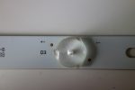
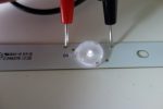
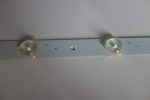
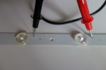
On a set of LED strips I salvaged, there are actually test points that are just openings in the solder mask.  By setting your DMM to diode test mode (or resistance at 2000 range), and touching the test points, the diode will glow if working.  Switch the polarities if it doesn’t seem to be working.  Also, don’t confuse the other dots for test points.  They are fiducials used for alignment by the pick and place machine when the strip was constructed and are not connected to anything.

If you don’t have test points, you can scrape a bit of the soldermask away on one side of the LED.  You just need to expose the copper underneath.  Since the LED’s are in series, you don’t need two scrapes for every LED, just one between each LED.

With a series circuit,  one LED going out will take out the whole strip.  I removed an LED from a spare strip from the same size TV I had and swapped it.  Replacement is a bit tricky since it is hard to align the LED with the narrow spacing on the pad so it is easy to short.  The LED’s also have different voltage and color temperature specifications so you need to find one similar.  The same brightness tested with the DMM will indicate it is a close match.

Strips are typically glued to the light box. and need to be remove with a scraper.  To remove the reflector sheet hiding the strips, flip the box over and use pliers to squeeze the end of the retention clips poking through that are holding the sheet down.

Update

Since I am seeing a lot more LED failures, I decided to buy a LED backlight tester from Banggood (was cheaper than ebay).  Make sure you get one that is 120VAC for North America and 200VDC max is usually good enough for TV backlight testing.

RCA RLDEDV3988-A Flickering Flashing Strobing Backlight

This TV had an unusual problem where the backlight would flicker on every second.  Researching on badcaps indicated the problem could be a blown resistor, the ADJ/DIM signal or bad LED.  It uses an AUO T390HVN01.0 panel and may have the same design as Proscan PLDED3996A-C

For an LED TV, the RCA was unusually thick.  The panel uses the box for a LCD backlight but with LED’s instead.  The TV also has just one combined main and power supply board and a built in DVD player.  I checked the menus for a backlight control but didn’t find one.

Taking the TV apart, there are many different screws so it would’ve been wise to mark where each type came from.  Viewing the TV from the back confirmed the backlight was flashing.  From the main board, there were 3 pairs of thin red/black wires going to the back of the panel and I assumed these were powering the LED strips used for the backlight.  I measured about 25V steady on each red wire.

To look at the backlight, I removed the front bezel, lifted the panel and took a peek.  The backlight configuration were three rows of ten LED strips  The top row was out.

To get better access, I totally removed the LCD panel and diffuser panels.  The circuit boards were attached to the bottom by double stick tape and had to be gently pried off.  When I powered the TV up (with the panel disconnected), the working LED’s remained on but at low brightness.

With the power off, I had to determine which LED was out since they were in series like christmas lights.  Some strips have test points marked with a plus and minus.  If you set your DMM to diode test mode, you can confirm the diode is good since it will glow.  The strips in this TV didn’t have test points so I scratched the side of the LED with a razor blade to expose the copper.  You only need to do this once between each LED since they are connected in series.

I was able to find the dead LED and had previously salvaged a working strip from another TV.  The replacement strip glowed the same brightness with the DMM test so I assumed it was suitable.  To remove the LED, you need to pop off the lens and then glob some solder to pop it off.  After 4-5 attempts and 2 LEDs later, I was able to get the replacement installed.  The spacing between pads is very narrow and would short across if it wasn’t aligned perfectly.

Plugging the TV back in, all three strips were now glowing.  When I put the LCD panel back in, I realized I wasn’t careful enough and had cracked the LCD panel.  When removing it, I had grabbed it by the sides and it flexed quite a bit.  I had also kept all the layers together hoping to minimize dust getting on it.  This actually caused it to flex more because of the weight.

Putting the TV back together, I realized what I should have done.  With the front bezel removed, the LCD panel is actually free after prying off the circuit boards and disconnecting the LVDS connector.  At this point I should have slid a stiff piece of cardboard underneath the panel and put it away somewhere safe.  I could then unscrew the bottom bezel that was still holding the backlight diffuser panels.
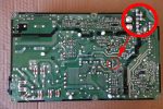
Philips 32PFL3505D/F7 Logo Appears and Shuts Off

After I thought I fixed this TV (see post here), I ran it for a couple of hours without a problem.  When I turned the TV off and back on, the Philips logo appeared and the TV shut off.  This was a sign the TV was going into protection mode.

An old post on a Philips TV forum indicated the PROTECT3 line from the inverter board was causing the shutdown.  I measured 0V with the backlight on and 0.8V when the TV was shutdown.  From the schematic, the line should be 3.4V during normal operation.  Looking at the schematic, there were three circuits that tested overvoltage on that line each with a transistor to pull PROTECT3 to ground.  Measuring the bases of all three pointed to Q1972 was being switched on during power up.  The base of this transistor comes from a 100VDC rail which is divided down (0.31x) and passed through a 33V (30.32-31.88V in the datasheet) zener diode D1971 (33BSB-T26).  I measured 28.7V at the cathode of the diode which is less than the specified breakdown voltage.  I lifted one end of the diode and confirmed the TV did not go into protection mode and the voltage was the same.

I ordered some BZX55/C33 33V zeners (+/-5% tolerance, 31.35 – 34.65V) on Ebay but found 1N5257B (+/-5% 500mW, DO-35) locally.  ECG5036A is another 5% substitue.  Part 568-5899-1-ND (2% tolerance 31.2 – 32.6V) at Digikey is a closer match to the original.

Update: A post on badcaps indicated the power rail should be 82V and not 100V which is caused by a bad Q1970.